GPS_DAO - APPLICATION TO USE GPS FOR TOPOGRAPHIC AND CADASTRAL PLANSMoha ELAYACHI, Hicham SALIMI and Said SOUHAILI, MoroccoKey words: GPS, Land surveying, GPS_DAO, topographic and cadastral plans. INTRODUCTIONThe Global Positioning System (GPS) was developed by the U.S.D.O.D, United States Department Of Defense, to support military applications (Logsdon 1992). But recently, the civilian users stretch the limits of this technology and they explore its suitability for civil applications. Some of the nonmilitary uses of GPS can be listed below:
Civilian users, surveyors in particular, have known that GPS can replace conventional surveys employing a theodolite and level or a total station because this technology that has been extended and used in various fields measures geographical coordinates, velocity and time with astonishing speed and accuracy. Its effects in research field become also important. The use of GPS technique in land surveying proved a great efficiency and permitted to accelerate data acquisition and maintained the accuracy needed for topographic plans. The aim of this study is to conceive a new methodology to set up, automatically, topographic and cadastral plans from survey data files obtained with GPS method. Within the section of topography, at the IAV Hassan II Institute, after purchasing an Ashtech Z-surveyor GPS, we conducted a research designed to develop software for setting up topographic and cadastral plans by using this new technology. The application so called GPS_DAO, developed within section of topography includes three important tasks:
The principal hardware and software packages used in developing this application and the adopted methodology for the proposed scheme will be described in this paper. The results of GPS_DAO application will also be discussed. PRINCIPAL HARDWAREThe most important decision that surveyor has to make is to choose the right survey software. But, he must initially choose the suitable hardware causing changes in the way he works. For that raison, it's necessary to present in the first time the hardware components. The first hardware party used in this research is the Z-surveyor GPS receivers and their antennas. This system supports collection and post processing of static, rapid static, and kinematics data. It uses twelve channels for Coarse/Acquisition, code phase, and carrier phase measurements on the L1, and precise (P) code phase and carrier phase measurement on L1 and L2 bands (Ashtech, 1998). The receiver operates as a reference or over station. The amount of data that can be stored in the Z-surveyor depends on the internal PCMCIA card (from 2Mb to 85M). The second party is the computer with these recommended characteristics:
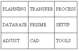
SOFTWARE PACKAGESIn order to, effectively, explore the presented hardware, we have to choose the suitable and require software. On the way, we used WinPrism, an Ashtech GPS survey software, that allows us planning and processing collected data by GPS and Glonass-GPS receivers (Ashtech, 1998). This software uses a system of different interface packages fully compatible, enabling us to handle in a softly manner its modules (figure 1): Planning, Transfer, Process, Database, Setup, Adjust, CAD, and Tools.
Figure 1: WinPrism modules Each module can be described bellow:
Other software components used in this study are AutoCAD drawing environment and Visual Basic. AutoCAD program is adopted for design process so as to establish topographic and cadastral plans. Every one, is familiar with engineering design procedures inside AutoCAD system, for this reason we incorporate it in our application. In addition if we want to make our job faster and easier with AutoCAD, we have to use another professional programming tool, Visual Basic, for creating and maintaining the calculating and processing modules of GPS_DAO. THE METHODOLOGYApplying GPS technology to setting up topographic and cadastral plans in Morocco is of a great importance for private and public surveyors. Their major purpose is to take advantage of the increase of technology. In addition the conventional measurement, user friendly methods, often have significant problems. Therefore, we proposed a new methodology for GPS surveying to overcome some difficulties of conventional approach. More efficiency can be achieved if we deal with the following steps. OBSERVING SCHEDULEReconnaissanceIn the first time we must use a topographic map at 1/50.000 scale (case of Morocco) in order to plot all potential control geodetic points that exist on the area to be surveyed. This map also provides a wide variety of required information like: location of power lines, boundaries, roads and buildings. Secondly, a preliminary visit to the site of survey is necessary and recommended. Then general information about topography of area and density of area features can be obtained. After these two stages, we must make sketches of details to survey including name of parcels, name of roads and name of natural limits. Planning missionAll GPS receivers require free sight to the satellite and four satellites at least must be above an observer's horizon. Then we have some conditions we have to become aware of to determine a good observing mission by using the planning software GPS (Sickle, 1996).
Observing missionChoosing the right GPS positioning method for a particular survey application is very interesting. It depends on the accuracy the user needs. This part is intended to offer some general guidelines that are used in our methodology.
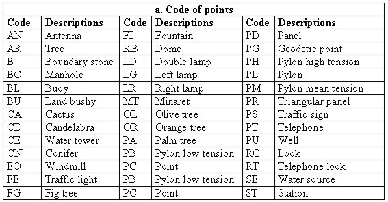
Table 1.a : List of code points
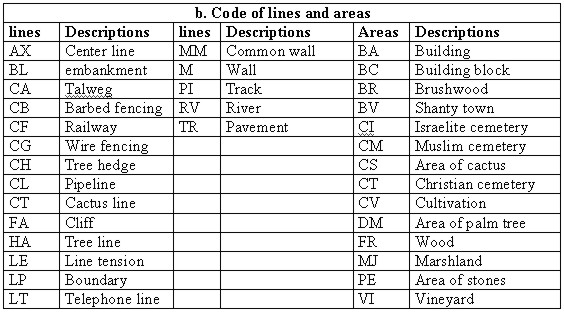
Table 1.b : List of code lines and areas
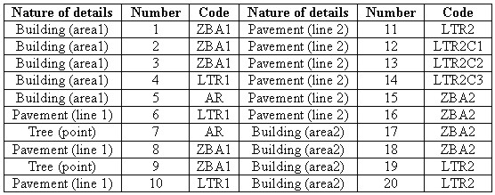
Table 2. Surveyed details with their codes.
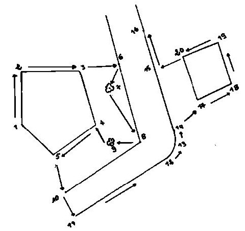
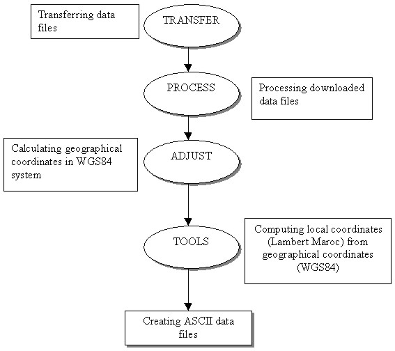
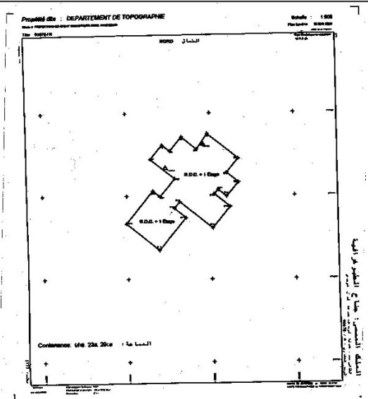
Figure 2: The approach to organize collecting data into the field or after downloading observations. POST MISSION PROCESSINGData processingAfter collecting observations, we proceed by importing data files into WinPrism software, calculating the geographical co-ordinates of transferred data and computing local co-ordinates (figure 3). Designing of topographical and cadastral plansAfter data processing, we transfer ASCII files to the database and we begin the concept of designing topographical and cadastral plans. In the first step, we take care for the rules made by the Administration of land titling, cadastral mapping and cartography according to the specific standards adopted in Morocco for setting up any graphic or textual documents. In the second step, the huge amount of downloaded data must be arranged and checked. With the managed database we are able to establish suitable plans (figure 4).
Figure 3: flow chart of different stages to undertake data processing (WinPrism)
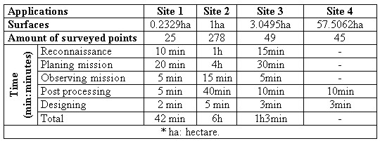
Figure 4: cadastral plan of department of topography RESULTS OF CASE STUDIESThe developed application has been tested not only into our Institute's campus but also in the other fields so as to improve the suitability of the tool for different surfaces, shapes, and kinds of boundaries. Four sites have been chosen and the time of realization has been taken in consideration. The obtained results are in norms adopted in Morocco (10 cm for relative accuracy). The following table 3 shows us the past times to designing topographical or cadastral plans by the proposed tool.
Table 3: Estimation of past time to surveying sites CONCLUSIONWe are proposing a methodology for establishing topographical and cadastral plans by using the new technology: GPS and CAD drawing environment. This new investigation allows us to enhance the manner of working. The obtained results are very satisfying and we are absolutely sure that surveyors will alter the conventional procedures and they will take advantage of the new tool. Using this method, it is seen that the survey labor has been certainly reduced comparing to conventional methods. On the other hand, the stop and go mode of GPS survey affords the desired accuracy and the use of intelligent code in field is successful. To adopt this method, it's necessary that the staff have to be well trained. Through this education we have not seen any bad results, but the following works have to be accomplished:
REFERENCESAshtech, 1998, Introduction to WinPrism, User's guide, USA, Magellan Corporation. Ashtech, 1998, Z-surveyor&Z-FX, operation and reference manual, USA, Magellan Corporation. Hansen, Su., 1998, GPS applied in cadastral surveys, proceeding of the FIG International Congress, commission 7, Juily98, Brighton, Great Britain. Leick, A., 1995, GPS satellite surveying, second edition, ORONO, John Wiley & Sons, Inc., USA Leick, A., 1995, Processing GPS carrier phases, GPS satellite surveying, pp. 317-409, second edition, ORONO, John Wiley & Sons, Inc., USA Logsdom, T., 1992, The science of navigation: The NAVSTAR Global Positioning System, pp. 01-16, California, Van Nostrand Reinhold (VNR), USA. Miura, S., 1997, GPS construction applications in Japan, Professional Surveyor, pp. 18-20, Vol.17, Num.7, October97, USA. Peling, Al., 1998, Trimble GPS Total Station 4800, Professional Surveyor, pp.54-56, Vol.17, Num.7, USA. Salimi, H.& Souhaili, S., 2000, Conception d'une méthodologie d'établissement automatique des plans topographiques à partir des fichiers GPS, Mémoire de 3e cycle, Département de Géodésie et Topographie, IAV HassanII, Maroc. Sickle, V., 1996, Planing a survey, GPS for land surveyors, pp. 137-167, Michigan, Ann Arbor Press, Inc., USA. BIOGRAPHICAL NOTEMoha Elayachi holds diploma of Engineer in geodetic and topographic sciences in 1995. His research was about conceiving and development of a cadastral database. He conducts research in the area of cadastral information systems and using GPS for land surveying. He is teaching astronomy and adjustment computation. Currently, he is a graduate student at the "Institut Agronomique et Vétérinaire Hassan II" where he pursues research on "investigation of a new approach of conceiving geographical information system related to the cadastral field". Hicham Salimi and Said Souhaili received their diplomas of Engineer in geodetic and topographic sciences in 2000 with a focus on applying GPS for surveying. Currently, they are with ADM society (the Moroccan Society of Motorways) as surveyors and they provide technical procedures on roads monitoring. CONTACTMoha Elayachi Hicham Salimi & Said Souhaili 19 April 2001 This page is maintained by the FIG Office. Last revised on 15-03-16. |