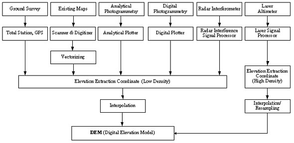
STUDY ON GEOGRAPHIC INFORMATION PRODUCTION USING AIRBORNE LASER SCANNINGJeongheon SEO and Sangdeuk HAN, KoreaKey words: ALMS(Airborne Laser Mapping System), DEM(Digital Elevation Model), DSM(Digital Surface Model), DTM(Digital Terrain Model), Photogrammetry. AbstractObtaining and managing accurate information is most important in the 21st century. Airborne Laser Mapping System (ALMS) provides better accuracy than other photogrammetry data. The study shown in this paper suggests the superiority of ALMS above other photogrammetry methods. This paper deals with ALSM which is being rapidly developed last few years provides us high density and accurate DTM and DSM and furthermore, the way ALSM can contribute to the study NGIS Implementation. 1. INTRODUCTIONIn the knowledge based, information-oriented 21st century, obtaining and management of accurate information is most important. The government has started to implement geospatial information from 1995 (1st National Geographic Information System Implementation Plan) and implemented 2nd phase NGIS Plan. Especially, NGI (National Geography Institute) has implemented the core National Framework Data and plans to provide these data to various local government, private, and research institutes. Photogrammetry is used in digital mapping, ortho image making and digital elevation data building. The current digital photogrammetry has advantages in cost reduction, increased operation efficiency, automation, and outcome consistancy. However, usage of digital photogrammetry has low accuracy especially in automated process of digital elevation data in the low texture area, built up area. In this area, much relief displacement is found and there is lots of shadowed area. Many efforts have been made to improve the current photogrammetry problems written as the above and automatically produce digital elevation data. The foremost outcome of this effort is LiDAR (Light Detection and Ranging) System. LiDAR is also called ALMS (Airborne Laser Mapping System). The actual development of ALMS started in late 1980's and commercially applied in mid of 1990's. After the outcome of the commercial product, constant endeavor for performance upgrading, accuracy improvement, data process and application betterment has made way for the usage of ALMS. This study deals with current ALMS technology, comparison and analysis of former digital elevation data, propriety of domestic introduction, the way to improve ALMS operation process, technology for accuracy improvement and how data built by ALMS can be applied to NGIS Implementation. 2. THEORETICAL BACKGROUND2.1 Existing DEM Production MethodsDEM (Digital Elevation Model) was introduced by C.L.Miller in America in 1958. He applied the DEM on designing roads. From then, DEM is applied in many fields such as Land planning, engineering, environment, resource, and telecommunication. DEM data are completed and widely used in many advanced countries (NGI, 1998). There are 4 ways in implementing DEM. They are by ground survey, existing maps and photogrammetry. Currently radar interferometer and laser altimeter is being developed. These are coming into practice. <Fig. 2-1>
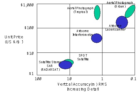
Fig. 2-1. Various ways in producing DEM When digitizing a paper map you use a scanner to scan contour lines of the publishing plate or directly scan the map. In case of digital maps, you use contour layers. Automated elevation extraction is possible by the latest automated matching technique. This technique enables more faster extraction than analytical photogrammetry. The advantage of digital photogrammetry is that it can use satellite imagery as well as aerial photographic scanned image. To measure elevation, we use inteferometric effect from a pair of satellite SAR imagery for the same area. This technique uses the characteristics of electromagnetic waves that it permeates clouds or rain without signal loss. Radiation and reflection rate of electromagnetic waves mostly depend on electric characteristics. Laser altimeter is not influenced by weather and can permeate woods and forest. As a result, it is used for mapping forest, woods and swamps. ALMS is favorable concerning that it is 4 (four) times more faster and economic than aerial photogrammetry. Cost for production of LiDAR DEM is about 500$ per square mile. Mercer evaluated that this is much better a DEM than USGS level 1 or 2 but is more expensive. <Fig. 2-2>
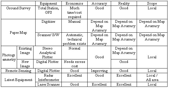
Fig. 2-2. DEM cost depending on accuracy. 2.2 ALMSSince 1961 when gas laser was developed, many safe and long-life products have been produced. Starting early 1970, laser has been used for physical process, lining and measurement. Ground elevation is calculated using the distance from a spatial point with known coordinates to the ground point. Laser reflection time from the ground is used to calculate the distance. In the 1980's there were no equipments that could exactly figure out the position of the plane except mechanical INS (Inertial Navigation System). So ALMS had not commercial successful. Late 1980's saw GPS usage and resulted many studies about laser profile. Reaching the middle 1990's commercial products using laser scanner came into use and therefore ALMS was possible. Table 2-1. The characteristics by DEM building methods.
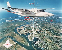
Generally, ALMS is composed of laser scanner, GPS, INS, computer H/W and S/W. Elements influencing the data accuracy are laser system (GPS+INS), data logging and the surface condition. Geographic features is found using approved air spatial point location, angle related to GPS and INS, and distance from reflection time. <Fig. 2-3>
Fig. 2-3. Principle of ALMS Logging data works with GPS time tag independently. GPS and INS constant error are reduced by strip adjustment algorithm. DEM(Digital Elevation Model) is built by the following two steps; First, removing buildings and vegetation with grid filtering process and second, converting the result to grid format. In case of aerial photogrammetry, coordinate of the ground feature is obtained with a pair of image taken in good weather. But this passive sensor system, aerial photographic camera takes a picture of the forest but not the ground below. The shadow of the trees makes picture taking impossible. Also in the built up area, tall buildings shadow out the lower buildings in the aerial image. However, ALMS have active sensor system that is not influenced by weather conditions and has little shadowed area. Laser scanner provides direction and distance. GPS, the position and INS, the vector direction. ALMS has some advantages compared with existing aerial photogrammetry and ground survey; First, vertical accuracy is 10 to 20cm and data correction in forest and urban areas is high. Second, workability is very high owing to automated process. Third, data logging average 60,000 /s or 120,000?/s at most. Control points are not needed in case of coast and swamp areas. Fourth, ALMS shows flexibility in data integration in its capacity of implementing DEM, DTM, DSM. Fifth, transformation into various format is possible for the absolute position (X,Y,Z) and height of collected data of buildings and vegetation are in binary or ASCII format. Sixth, installing ALMS equipment on various planes is simple and takes less than 2 hours. 2.3 Experimental study and development of ALMS technology2.3.1 Experimental study This study chose Bundang area which has diverse geographic features to establish ALMS operation process appropriate for geographic features in Korea. The ALTM 1020 airborne laser scanner produced by Optech in Canada was installed on a PA-31-350 plane. Detailed analysis of DEM needs is required for DEM accuracy and density differs by application. By this analysis, a plan for data logging can be established. Accuracy, suitability to NIG's standards has to be set based on data process. Contribution to the 2nd NGIS implementation is considered as well as data logging possibility and workability to build 3D GIS database, development of ALMS technology. Table 2-2. Targets of ALMS experimental study.
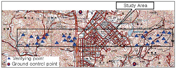
To satisfy the acquirements, targets of experimental study are as table 2-2. Study area in Bundang selected as the subject is 11 km wide from east to west and 0.8 km from south to north, 8.8 km2 in size. Evenly spread 20 verifying points in this area were chosen. <Fig. 2-4>
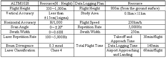
Fig. 2-4. Position of verifying and Ground control point in the study area. 2.3.2 Field Checking and Ground Survey Plans Field checking is done at control and verifying points chosen during map planning. Position and situation of these control and verifying points were confirmed. Also condition of GPS signal reception was checked. Investigation is made on geographic features that influence ALMS such as rivers and lakes. Power transmission towers, church tops and water tanks are surveyed as special features. This study chose 2 control points and 28 verifying points. Ground control points, verifying points, profiles, breakpoints based on field checking for ground survey are confirmed. The equipment for ground survey is GPS in general but Total Station or Auto Level is used at times. The equipment for this research is as table 2-3. Table 2-3. Specification of ALTM 1020.
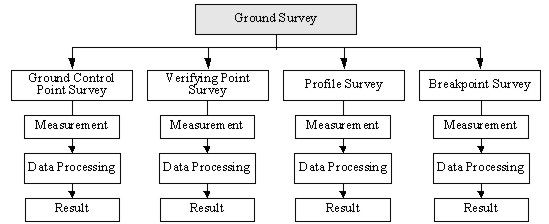
2.3.3 Ground Survey Ground survey classifies into ground control points, verifying points, profiles and breakpoints survey. <Fig. 2-5> Ground control points survey is done to acquire accurate position which is necessary for DGPS. Verifying points survey uses kinematical GPS survey which is used to verify accuracy of ALMS.
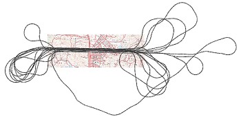
Fig. 2-5. Specific process of ground photogrammetry Profiles are taken at grounds and pavements which have little gradient. Profiles are applied for vertical accuracy improvement. Measurements were done by kinematical GPS surveying every 5~10m in a flat area with a length of 100m. This research surveyed 3 profiles along the river bank and roads. Verifying points are taken at tombs in case of mountain areas where effects from surroundings are small. This experimental study chose 28 verifying points. 2.3.4 ALMS (Airborne Laser Mapping System) Survey The process of ALMS is in two steps which are first, equipment installation and calibration and second, airborne laser scanning. These two steps require GPS base station running at ground control points for DGPS. Equipment installed on the plane is an integrated system composed of laser scanner, computer, GPS, INS, and navigation system. Logging ALMS data needs much time. For this experimental study Kimpo airport was the takeoff point and it took 20 minutes to get to the Bundang area. The ALMS flight route is shown in <Fig. 2-6>.
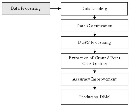
Fig. 2-6. The study area and flight route While scanning, after surveying one route the plane has to change the direction of the plane to start surveying another. If a sudden change in direction is made, the accuracy of IMU draws a sudden decline. To avoid this to happen, no more than 15 degree change of direction can be made. For accurate position improvement, GPS control points were installed near the study area and DGPS survey was done. In this study, GPS signals from two NIG's 4th order triangular system were taken every second as soon as the takeoff. 2.3.5 Data Processing Through ALMS survey, laser distance data, INS data, GPS data received on the plane and DGPS data received at the base station. Data loading means transferring ALMS data onto the computer. <Fig. 2-7>
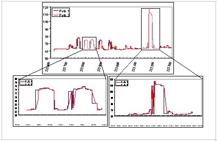
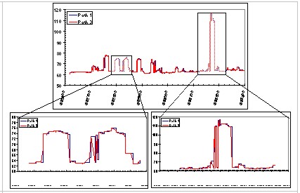
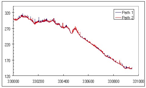
Fig. 2-7. Specific data processing GPS, INS and laser distance data loaded on the computer are classified according to projects and passes. For accuracy of ALMS data, PDOP of GPS must be below 5 and 1~3 is most appropriate. Adjustment of GPS data received on the plane is done by DGPS in case PDOP is good. The position and vector direction of the laser scanner are calculated from GPS and INS data. Every ground point position is calculated by the laser distance with the data resulted above. A group of ground points is called 'point cloud'. The vertical accuracy of position is good in 15cm but horizontal accuracy is generally low when flight height is around 800m. 3 profiles were surveyed and adjustment of vertical accuracy was made with these profiles. Boundary of man-made feature was referenced to correct horizontal accuracy. Two new algorithms were developed; boundary extraction from point cloud data and pass adjustment with point layer. <Fig. 2-8>
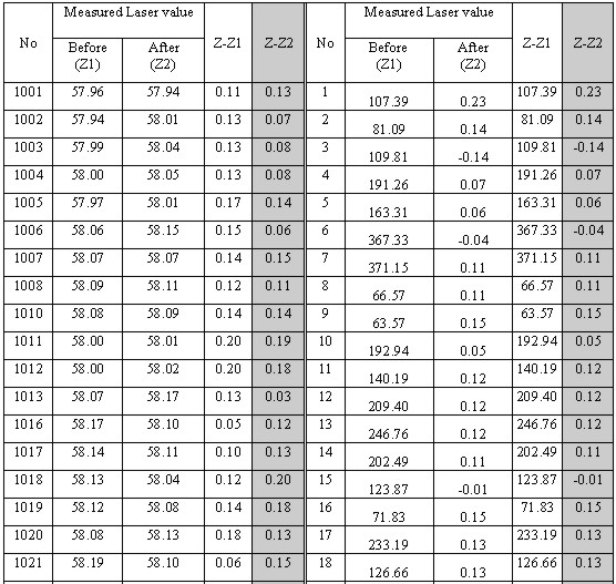
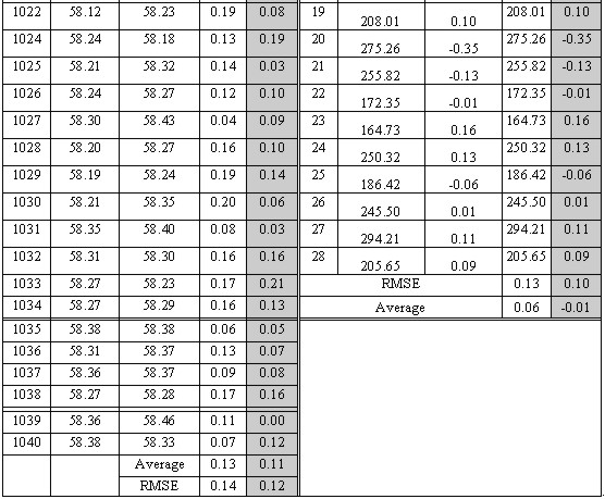
Fig. 2-8. Comparison of before and after adjustment 3. RESULTS AND CONCLUSION3.1 Accuracy EvaluationThis study compared the 'z' value of DEM with surveyed data of verifying points and profile coordinates. Before adjustment, RMSE was 0.14 m with profile data and 0.13 m with verifying points. After, RMSE value came to be 0.12 m with profile data and 0.10 m with verifying points. Table 3-1. RMSE before and after profile / verifying point adjustment
3.2 Producing mapsAnalysis and experiment on bird eye view, contour line, slope map, topography map, relief shade map and color shade map by height using DEM was done in this study. All the maps mentioned above used DSM and DEM of the built up and mountain area. The quality of real world image was improved by bird eye view produced from DSM fused with MK-4 and SPOT images. This excellent fusion will be very useful in producing cyber world or ortho photographic map. The DSM was compared to NGI's 1/1000 digital map to verify the relative accuracy. Relative accuracy of DSM is good enough but the contour line accuracy of digital maps has 'z' value error of more than 5m. 3.3 Results and SuggestionALMS is becoming more and more important in the survey method for it is a automated surveying technique. The analysis and comparison of efficiency and applicability of survey systems shows that ALMS is most suitable to produce DEM considering economics, workability and accuracy. The high density DEM produced by ALMS has high workability. The quality of this map is impossible to produce by photogrammetry. Producing highly precise DEM in the mountain and built up area by existing survey technology and ALMS data processing is evaluated to be cheaper than existing measurement methods. Data processed with Lasermap Image Plus has vertical error(±14cm), horizontal error(±40cm). And The Mobile Mapper improved the vertical error to less than ±10cm, horizontal error to less than ±20cm after adjustment and developed technique that automatically produces DEM, DTM from DSM. Based on this developed technique, The Mobile Mapper established the ALMS operation process for domestic use. The accuracy of DEM made by ALMS cannot be overcome by large scale maps or photogrammetry. ALMS can be used in 3D urban modeling, electromagnetic wave analysis, and image map production. Starting from 2001, the second NGIS mainframe is implementing basic geographic information system for the common user which include the government, private, and research institutes. Therefore accuracy and reliance in basic geographic data is necessary and prompt production, update of the data is needed. DEM made by ALMS satisfies these demands. ALMS is sure to advance the schedule in application of GIS in various fields (such as flood loss calculation, water resource management, road planning, earthwork amount calculation, wood management). ALMS is thought to an effective alternative technology for implementing national basic geographic information for a 21 century digital nation. REFERENCES
BIOGRAPHICAL NOTEJeong Heon Seo Sang Deuk Han CONTACTJeongheon Seo Sangdeuk Han 19 April 2001 This page is maintained by the FIG Office. Last revised on 15-03-16. |